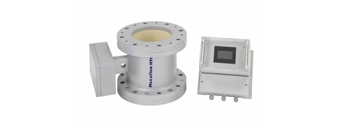
 Figure 1. Example of MaxxFlow installation
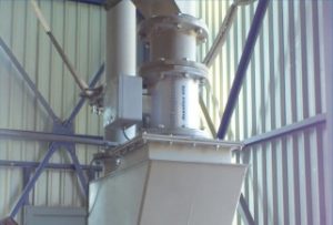
The MaxxFlow by Envea (formerly SWR) is suitable for measuring the flow of large amounts of dry solid (non-metallic) bulk goods. The MaxxFlow is installed on round pipelines or ducts. Its open construction and compact form, combined with very high throughput capacity, make the MaxxFlow usable in situations where previously only complex mechanical systems, such as weighing bunkers or fall plates, were applicable. The flowmeter is always placed after a mechanical transport system (conveyor). Examples include rotary transport systems (figure 2), screw conveyors (figure 3), air slides, or chain conveyors.
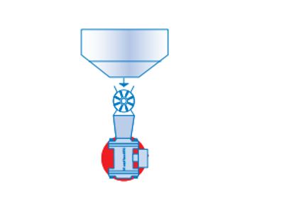 Figure 2. Installation after a rotary transport system
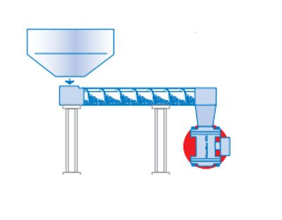 Figure 3. Installation after a screw conveyor
Function
After the transport system, the material to be measured falls/slides through the MaxxFlow’s opening past the sensor. During the material’s passage, the sensor in the MaxxFlow measures the type of material and its velocity. As the material falls from a constant height after leaving the transport system, the flow velocity accelerates. However, the velocity remains constant at the sensor installation position, eliminating the need for continuous velocity measurement. The velocity is dependent on the height from which the material falls.
A homogeneous measurement field is generated in the measuring tube via an input coupling of a high-frequency, electromagnetic alternating field. The measuring tube is made of wear-resistant Al2O3 (aluminum oxide) ceramic. Dry bulk materials in the measuring field reduce the amplitude of the electromagnetic alternating field, resulting in a measurement signal that depends on the concentration of bulk materials in the sensor (i.e., bulk density, expressed in kg/m3).
When the material velocity in the pipeline changes, such as from a change in initial speed, this can also be measured through transit-time measurement using two additional electrodes behind the ceramic measuring tube.
Mass Flow Calculation
Several variables are needed to calculate the mass flow, which the MaxxFlow determines using its sensor:
Speed formula*:
V = √ (2 x g x h)
Mass flow formula*:
Q = K x V x A
*Formula abbreviations:
- Q (kg/s) = Mass flow
- K (kg/m³) = Density
- V (m/s) = Velocity
- A (m²) = Area
- g = gravitational acceleration
- h = fall height
Calibration
Determining the material velocity in the pipeline is independent of the type of bulk material being measured. The velocity can be calculated using the formula above or transit-time measurement, so speed measurement does not require calibration.
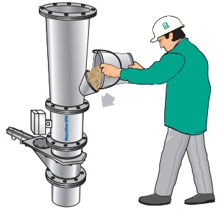 Figure 4. A material sample is poured into the sensor for calibration. The slide gate beneath the sensor is closed.
A simple calibration method is possible. A material sample (~10 liters = sensor volume) can be poured into the sensor through a filling funnel above the sensor. A slide gate at the bottom of the sensor can be closed for calibration. When the sensor is completely full, the measured density value should match the material density. The bulk material’s density can be determined as grams per liter and input into the evaluation unit. Even with large product flows, the measurement can be fully calibrated with a material sample of approximately 10 liters, eliminating the need for active process testing or using tons of material as a reference.
System
A complete measuring system consists of two components:
- The MaxxFlow feeder for installation in the conveyor (with sensor)
- MFE 100 transmitter
The feeder is available in different sizes:
- DN 100mm
- DN 150mm
- DN 200mm
The transmitter (MFE 100) connects to the sensor via a 4-wire shielded cable. The maximum distance between the sensor and transmitter is 300 meters.
Configuration
For sensor configuration, it is important to know the maximum flow volume to ensure that the dry bulk material can flow through the sensor without hindrance or affecting the flow.
Example
If the maximum mass flow is 80 t/h, and the material has a density of 0.8 t/m³, the maximum volume flow will be 100 m³/h. Using a MaxxFlow DN 150mm requires a speed of 3 m/s, while a MaxxFlow DN 200mm requires a speed of 1.7 m/s. To achieve this, an opening of 0.5m for DN 150mm and 0.15m for DN 200mm is needed between the conveyor and the sensor.
Advantages of the MaxxFlow
- Installation is free from obstructions, preventing dead zones.
- Easy to install and adjust.
- Dust resistant.
- Maximum temperature up to 120°C.
- Pressure resistant up to 10 bar (on request).
- Wear-resistant ceramic inner pipe.
