
A turbine is designed to reach a maximum number of revolutions per minute (rpm), where the blades of the turbine can achieve enormous speeds. This limit must not be exceeded, as it would put too much stress on the turbine’s structure. When this limit is exceeded, it is called overspeed; the turbine is making too many revolutions per minute. Overspeed in a turbine can lead to very dangerous situations. Such situations can have catastrophic consequences for employees, the environment, and the factory. An (overspeed) monitoring system should shut down the turbine before it enters overspeed.
The monitoring system must be tested periodically to ensure that it has an adequate response speed if needed. This is mandated by various standards in the process industry:
- IEC 62061 – Functional Safety
- IEC 61511 – Functional Safety of safety systems in the process industry
- IEC 61508 – Functional Safety of electrical/electronic/programmable safety systems
This prevents (catastrophic) accidents. The frequency of these tests depends on the application and is often prescribed by the manufacturer in the system’s manual. However, a risk can never be completely eliminated. Risk mitigation is carried out according to the ALARP principle, or as low as reasonably practicable, meaning that the risk must be as low as is reasonably achievable.
The purpose of testing is to ensure that the likelihood of the monitoring system failing when an intervention is needed is minimized as much as possible. This so-called Probability of Failure on Demand (PFD) should be minimized to an acceptable risk. By testing the safety and alarm functions of the system at a predefined frequency, a company can demonstrate that it is doing everything possible to ensure state-of-the-art safety. This ensures compliance with the legal requirement to implement as many risk-reducing safety measures as possible and with the standards related to machine monitoring (IEC 61511, IEC 61508 & IEC 62061). Additionally, a safe work environment contributes to a positive corporate culture.
Safety Integrity Level (SIL)
The Safety Integrity Level (SIL) is part of Functional Safety. In a SIL-certified monitoring system, the maximum acceptable risk factor is always considered. How high this tolerable risk is depends on the SIL level, which in turn depends on the application. The higher the SIL level, the lower the tolerable risk. However, a higher SIL level is not always better. To maintain a certain SIL level, the functionalities of the entire loop must be tested. This can be done by conducting various proof tests.
Overspeed Monitoring System Testing
Testing an overspeed monitoring system can be done in various ways. There can be electronic overspeed testing and mechanical overspeed testing. There is a preference for electronic testing over mechanical testing for two main reasons:
- Mechanical testing can only be performed when the machine is offline, which incurs (unnecessary) high costs. Electronic testing allows the user to test the machines while they are operational.
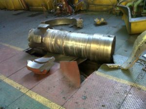
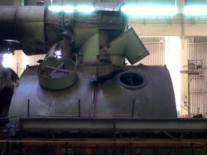
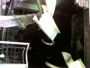
- In mechanical testing, the turbine must actually be brought to overspeed, creating an unsafe situation. If the overspeed monitoring system fails, it could lead to serious accidents. This was the case at the Duvha power station in South Africa, where the turbine was brought to overspeed during testing and exploded after four seconds (see images below).
Electronic overspeed monitoring allows the user to simulate overspeed during operation, allowing the turbine’s (artificial) tripping to be verified. There is equipment that enables the simulation of overspeed, allowing overspeed monitoring systems to be tested.
IST 101 Frequency Generator
The IST 101 is a compact 3-channel speed calibrator developed by Istec specialists for machine monitoring testing. The tool is designed to verify the functionality of overspeed monitoring systems, based on input from field service engineers. Most frequency generators lack three channels to check all functions related to overspeed, underspeed, and acceleration, but the IST 101 supports these. Through various test functions (2oo3, 3oo3, etc.), the IST 101 can, for example, simulate an overspeed situation and then test how the monitoring system responds. This way, actual overspeed does not need to be created, and dangerous situations are avoided. Furthermore, these tests can be carried out during operation, as the monitoring system reacts artificially and does not actually shut down the turbine. This saves significant costs, gives the user more control over the situation, and avoids hazards.
IST 101 Probe Adapter
The IST 101 Probe Adapter is designed to test speed sensors. The Probe Adapter can be connected to the IST 101 Frequency Generator. Both analog and digital speed sensors can be tested with the IST 101 Probe Adapter. The IST 101 Probe Adapter works as a 3-channel digital pole wheel. Together with the Frequency Generator, the adapter enables testing of an entire loop (including speed sensors). This allows for a full proof test to be carried out, ensuring a certain SIL level is maintained. It also avoids many of the dangerous situations that arise during mechanical testing. A relatively small investment compared to the risks associated with other methods. Additionally, the portability of both the Frequency Generator and the Probe Adapter ensures ease of use. A battery makes the Frequency Generator independent of power supply during use. The tools are energy-efficient, making them suitable for long-term use.
